On this page
Table of Contents
If you’re still building your foundation in basic electricity, start with this beginner-friendly overview: 🔹 “Electricity 101: The Complete Beginner’s Guide to How Power Really Works”
After reading it, the concepts in this article will make a lot more sense.
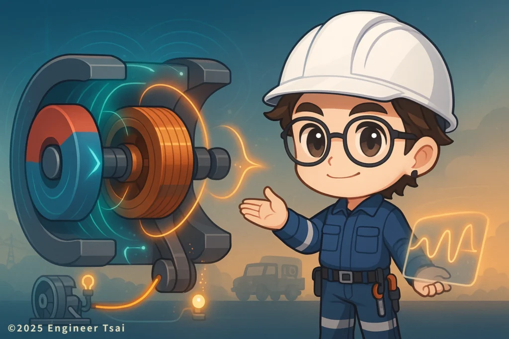
▶️ Watch first: What is a DC generator and how does it create “steady” DC?
How does a DC generator work? This short video gives you an intuitive feel for the DC generator working principle.
You’ll see a simple coil spinning in a magnetic field, creating an induced voltage. Then you’ll see how the commutator flips the connections so that the output you get is DC with a fixed direction instead of alternating back and forth.
What is a DC generator and how does a DC generator work? One-sentence version first
A DC generator is a machine that produces direct current (DC)—a voltage and current with a fixed direction and a controllable magnitude.
Physically, a DC generator is very similar to an AC generator. Both rely on Faraday’s law of electromagnetic induction:
when a conductor cuts through magnetic field lines, a voltage is induced in that conductor.
The key difference is that a DC generator adds a mechanical rectifier—usually a commutator with brushes—that takes the induced voltage (which naturally wants to be positive and negative in turn) and reconnects it so that the outside world sees one fixed polarity.
If you’re preparing for electrician licensing exams, studying electrical engineering, or thinking about switching into electrical work, getting the DC generator principle clear in your mind will make later topics—motors, drives, and power systems—feel like they’re all variations of the same idea. In other words, when someone asks “how does a DC generator work?”, you’ll be able to give a clear, one-sentence answer instead of just pointing at a diagram.
If you want a one-line memory hook for how a DC generator works:
You spin a coil in a magnetic field to create an AC-like voltage, then use a commutator to flip the connections every half turn, so the output you see is a single, fixed-direction DC waveform.
Breaking down the DC generator: main parts you should know
Whether it’s a small teaching demo in a lab or a rugged unit in older industrial or military equipment, a DC generator is built around a few key parts.
🔹 Rotor / Armature
The rotor (also called the armature) is the part that spins.
It usually consists of a laminated iron core with coils of wire wrapped around it. As this armature rotates in the magnetic field, the coil keeps cutting magnetic field lines, so the voltage induced in the coil changes with time.
🔹 Stator (Field)
The stator is the part that does not move. Its job is to provide a steady magnetic field.
That field can come from:
- Permanent magnets, or
- Electromagnets (field windings) that become magnetic when current flows through them.
From a design point of view, the more stable and stronger the stator field is, the easier it is to predict and control the voltage that the armature will generate.
🔹 Commutator
This is the biggest difference between a DC generator and an AC generator.
A commutator is a set of segmented copper rings mounted on the rotor shaft. Each segment is connected to different ends of the armature coils. Fixed carbon brushes rest on these segments as the shaft spins.
Every half turn, the commutator effectively reverses which coil end is connected to which brush. That means the part of the waveform that would have gone negative is flipped back to positive at the output terminals, so what you see from the outside looks like DC with a constant direction.
🔹 Brushes
The brushes are fixed in the housing and lightly press against the commutator. They are usually made of carbon or graphite.
Their job is simple but critical:
Collect the DC that the commutator has “sorted out” and deliver it to the external circuit.
You connect your load, lamps, or measuring instruments to these brush terminals.
Quick review of electromagnetic induction: where does the voltage come from?
As the armature coil spins in the magnetic field, the magnetic flux passing through the area of the coil is constantly changing.
By Faraday’s law of electromagnetic induction, whenever the magnetic flux linked with a coil changes over time, a voltage is induced across the coil terminals.
If we did not have a commutator, the induced voltage across the coil would look like an AC waveform:
- For part of the rotation it would be positive,
- For the opposite part it would be negative,
forming a symmetric AC voltage that swings above and below zero.
That’s the underlying physics behind every DC generator. The actual machine is just this basic experiment, made robust and packaged with a mechanical rectifier.
In a DC generator, we use the commutator to switch which coil end is connected to which brush every half turn. The part of the waveform that would have turned negative is flipped, so the voltage at the output terminals becomes a pulsating DC: always the same direction, but with ripples in its magnitude.
If you want to dive deeper into the formulas and diagrams, you can cross-check with external resources like the Wikipedia article on electromagnetic induction, and read this article side by side with those diagrams.
Commutator “magic”: turning AC inside into DC outside
Let’s imagine the simplest possible single-loop armature.
- As the loop spins in the magnetic field, the induced voltage in the coil changes with angle. Inside the coil, the voltage naturally wants to be an AC waveform, going positive and negative.
- The commutator connects each end of the coil to different copper segments. The brushes touch these segments.
- Every half turn, the coil physically swaps position in the field, but the brushes switch to the other segments, effectively flipping which coil end is treated as “positive” at the output.
The result:
- Inside the coil: the induced voltage is AC-like, alternating in sign.
- At the output terminals: the connections have been flipped just in time, so the outside world sees a pulsating DC—always the same polarity, but rising and falling in magnitude.
If you add capacitors, inductors, or other filtering circuits, you can smooth this pulsating DC to make it look closer to the “flat line” DC that you see from modern power supplies. This is common in teaching equipment, older lab supplies, and demonstration rigs.
Where do we still use DC generators today?
Modern large-scale power systems almost always use AC generators (alternators) plus electronic rectifiers instead of traditional DC generators. But once you have a basic answer in your head to the question “how does a DC generator work?”, you’ll start to notice places where DC generation—or the same principle—still shows up.
Here are some typical use cases:
- ✅ Older vehicles and military equipment
Early automotive and special-purpose military vehicles used DC generators to charge batteries and supply DC loads directly. Many of these have been replaced by alternators, but the principle is the same. - ✅ Electroplating and electrolysis plants
Processes like electroplating and electrolysis need DC with a fixed current direction. Historically, DC generators were used as the main source. Today they’re mostly replaced by AC plus rectifiers, but the underlying reason is the same: you need controlled DC. - ✅ Precision lab equipment and teaching demos
In university or trade-school labs, you may still find DC generators used to demonstrate the full chain: mechanical rotation → induced voltage → commutation to DC. - ✅ Technical training and licensing prep
In electrician apprenticeship programs, trade schools, and entry-level electrical engineering classes, the DC generator is still a classic example in machine theory. It’s a great tool for teaching both electromagnetic induction and basic machine construction. - ✅ Small wind / hand-crank generators and kits
Many hand-crank generators, camping gadgets, and STEM kits use either a DC generator or an AC machine with built-in rectification. You crank, the rotor spins, and you watch a small LED light up from the DC output.
If you want to see how DC generators fit into the wider family of electrical machines, you can also look up a simple overview of electrical generators and compare DC and AC designs on one page.
Why does DC feel so “stable”?
A lot of people picture DC as a perfectly flat line, like the output of a bench power supply.
A real DC generator, however, usually starts with pulsating DC: the direction of current is fixed, but the voltage still ripples up and down.
It feels “stable” for a few reasons:
- The direction is fixed by the commutator
Unlike AC, the current doesn’t reverse in the load. For many devices, having a fixed current direction is already a huge simplification. - Multiple coils and commutator segments smooth the ripple
In a practical DC generator, there are many armature coils and many commutator segments. At any given moment, different coils are at different positions in the field. When their outputs are combined, the ripples tend to overlap and average out, reducing the visible pulsation. - Filters and regulators smooth the waveform even more
Add capacitors, inductors, or voltage regulators, and you can turn the pulsating DC into a much smoother voltage—close to what we expect from a modern DC power supply.
Because of this, DC generators (or their modern electronic equivalents) are well-suited to applications that need a constant current direction, such as battery charging, certain control circuits, and older electrochemical processes. If you’ve ever wondered how a DC generator works in real-world gear, these are exactly the kinds of applications where that principle shows up.
DC generator vs. AC generator: common questions
If you searched for “how does a DC generator work”, chances are you also care about how it compares with AC generators in real power systems and exam questions. These FAQs connect the basic working principle to the kinds of things teachers, textbooks, and licensing boards like to ask.
Q1: What is the fundamental difference between a DC generator and an AC generator?
Short answer:
They both rely on the same induction process. The real difference is in how the output is handled.
In an AC generator, the machine simply sends the naturally alternating voltage out to the terminals. The external circuit sees a sine-wave AC voltage that swings positive and negative.
In a DC generator, the machine first creates an AC-like induced voltage inside the armature, then uses a commutator and brushes to flip the connections every half turn. The external circuit sees a pulsating DC voltage with a fixed polarity.
Q2: Why don’t modern power plants use DC generators anymore?
Two main reasons:
AC is easier to step up and step down
With transformers, it’s easy to raise or lower AC voltages. For long-distance transmission, you can increase voltage and lower current, cutting line losses.
Rectification is cheap and reliable now
Modern electronics makes it easy to convert AC to DC with high efficiency. So the typical setup is a large AC generator plus rectifiers, rather than a huge DC generator. It’s easier to build, maintain, and control.
Q3: Is the output of a DC generator perfectly flat DC?
No. A basic DC generator produces pulsating DC: the polarity is fixed, but the magnitude rises and falls.
By:
Increasing the number of coils and commutator segments, and
Adding capacitors, filters, or regulators,
you can make the output look much smoother and closer to the “flat” DC we imagine. But at its core, the raw output is still a rectified version of an AC-like waveform.
Q4: In school or licensing exams, what DC generator topics usually show up?
If you’re studying in a trade school, community college, or preparing for electrician / electrical engineering exams, the usual DC generator topics include:
Names and functions of the main parts: rotor (armature), stator (field), commutator, brushes.
Basic principle: changing magnetic flux → induced voltage → commutation to DC.
Simple equivalent circuits and voltage equations: terminal voltage, armature reaction, internal generated voltage.
Comparison with AC generators: where you’d choose DC, what the pros and cons are.
If you understand this article and then match it with your textbook formulas, you’ll be able to handle most DC generator questions you’re likely to see.
Q5: If I already understand AC generators, is learning DC generators still useful?
Yes—very.
One big insight is that DC generators, AC generators, transformers, and motors are all members of the same family.
Once you’re comfortable thinking in terms of:
“Changing magnetic flux → induced voltage or force”
you’ll find it easier to understand any machine that spins, generates, or drives a load. That’s incredibly helpful if you’re moving into electrical work, industrial maintenance, or any field that deals with real power equipment.
You stop just memorizing formulas and start recognizing what’s physically happening inside the machine.
Conclusion: what picture should pop into your head when you hear “DC generator”?
A DC generator may look like an old-school industrial machine, but the physics inside is the same as a simple coil-and-magnet bench experiment you can do on a desk.
If we compress the whole DC generator working principle into one idea and answer the question “how does a DC generator work?”, it’s this:
Take the basic “spinning coil in a magnetic field” experiment, scale it up, and add a commutator so the output becomes a useful DC source.
So next time you see someone cranking a small generator, or you spot a DC machine in a lab, you can silently narrate what’s happening:
It’s using electromagnetic induction to turn mechanical rotation into a directed flow of electrical energy.
Keep that mental picture. Whether you’re preparing for exams, building projects, or moving toward an electrical or electrician career path, any time you meet a machine that spins and supplies power, you’ll have a much stronger intuitive understanding of what’s going on inside.
Further reading
🔹 AC generator: how it produces electricity
Learn how large power systems use AC generators and why AC is the default for long-distance transmission.
🔹 What is electromagnetic induction? Faraday’s law explained
A deeper dive into “changing magnetic flux → induced voltage”, the foundation behind every generator and transformer.
Read next in this topic
- What Is Electricity ? Everything You Need to Know
- Current & Voltage for DIY Enthusiasts : Unlock the Basics
- AC vs DC: What’s the Difference and Why It Matters (From Phone Charging to 120 V Home Power)
- Basic Parts of an Electric Circuit (Power Source, Wires, Loads)
- Conductor vs Insulator: How Your Home’s Wiring Keeps You from Getting Shocked
- Ohm’s Law Explained: V = IR for 120V Home Circuits
- What Is a Resistor? How It Works, Types, and How to Choose the Right One
- Series vs Parallel Circuits: Simple Guide for Home Wiring (With Formulas & Examples)
- How Electromagnetic Wave and Electricity Shape Modern Technology
- What Is Voltage? Simple Definition, Everyday Examples, and Safety Tips
- What Is a Battery? How It Works, Types, and Everyday Uses Explained
- What Is Ampere’s Law? A Visual Guide to How Current Creates Magnetic Fields
- What Does a Capacitor Do? Uses, Energy Storage, and Everyday Examples
- Types of Electrical Wire: How to Choose the Right One for Your Home
- How AC Power Is Converted to DC: What’s Really Inside Your Phone Charger?
- Electrical Energy Conversion: How Energy Transforms for Everyday Use
- Magnetic Field and Current: The Core Relationship Behind Motors, Generators, and Wireless Charging
- How Do Magnets Work? From Fridge Magnets to Maglev Trains
- What Is Inductance? Inductor Basics for Real-World Circuits
- What Is Impedance? A Plain-Language Guide to Resistance, Inductive Reactance, and Capacitive Reactance