On this page
Table of Contents
If you’re still building your foundation in basic electricity, start with this beginner-friendly overview: 🔹 “Electricity 101: The Complete Beginner’s Guide to How Power Really Works”
After reading it, the concepts in this article will make a lot more sense.
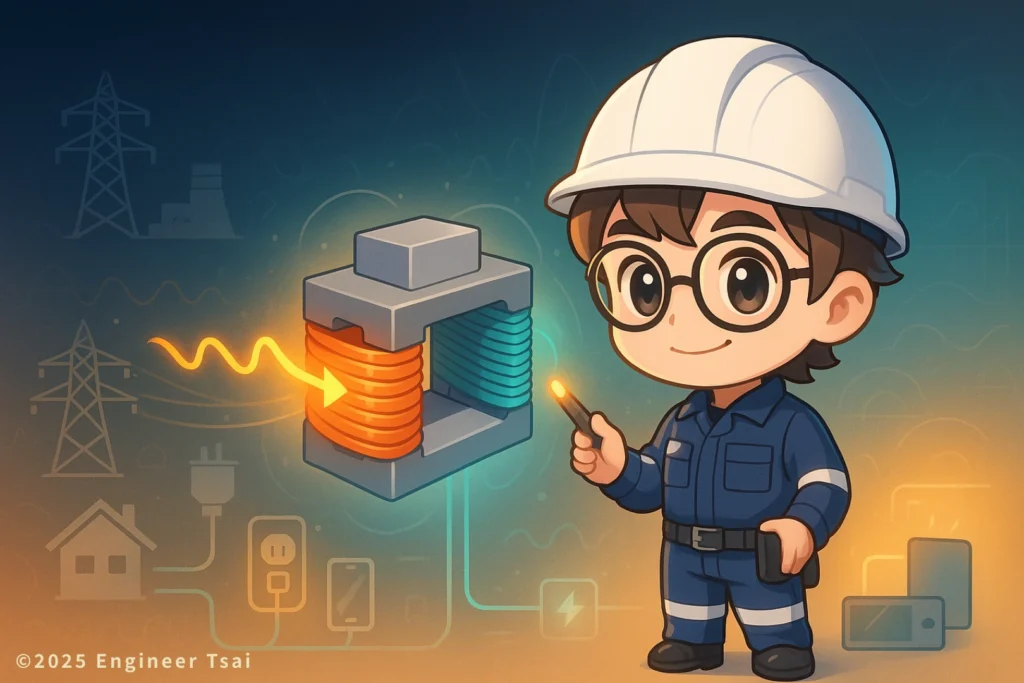
How a transformer works is not as scary as it sounds. Once you grab two key ideas – electromagnetic induction + turns ratio – you can understand everything from the big transformer can on a pole in your neighborhood to the tiny transformer hiding inside your phone charger, and why both can turn the voltage into something “just right” for the job.
Watch now: how a transformer works from power lines to phone chargers
This short video gives you a friendly, real-life explanation of a transformer, showing how a transformer works using electromagnetic induction to change voltage, so power can travel from a power plant through the grid all the way to your home, then become the right voltage for phone chargers, AC units, computers and more.
What is a transformer? One sentence to explain how it works
If someone asks you: “So what exactly is a transformer?” you can start with this:
A transformer is an electrical device that uses electromagnetic induction to convert AC voltage from one level to another.
It relies on a primary winding, secondary winding and magnetic core to change voltage, so power can be sent long distances efficiently and then used safely in household appliances and other equipment. That’s the heart of how a transformer works.
Basic idea of a transformer (with everyday U.S. examples)
In a typical U.S. home, almost every part of your electrical system depends on transformers: the gray can on a utility pole in your neighborhood, pad-mounted transformers in a subdivision, temporary power transformers on construction sites, and the small transformer inside your laptop or phone charger. Behind all of them is the same how a transformer works principle.
From an engineering point of view, a transformer is a device based on electromagnetic induction. Most power transformers you see are built from:
- Primary winding: connected to the input voltage side – this is where you “feed power in.”
- Secondary winding: connected to the output side – this is where you “take the adjusted voltage out.”
- Core: a magnetic path that keeps the flux confined and boosts energy transfer efficiency.
The two windings don’t need a direct electrical connection. Instead, they hand energy off through a changing magnetic field in the core – that’s why transformers can also provide galvanic isolation, improving safety and noise immunity. All of this is how a real transformer behaves in practice.
Common uses for transformers include:
- Stepping voltage up (step-up transformer): raise generator or distribution voltage so power can travel long distances with less current and lower line losses.
- Stepping voltage down (step-down transformer): drop utility voltage (for example 120/240 V in the U.S.) to 24 V, 12 V, 5 V and other safer levels used in appliances, electronics and control circuits.
- Electrical isolation: let the primary and secondary “see” each other magnetically but not touch electrically, improving safety and signal stability.
1. AC is what makes a transformer work
AC and how a transformer works
There’s a very important point: a transformer only works properly with AC (alternating current). It does not directly work with steady DC (direct current).
The reason is simple: a transformer depends on a changing magnetic field, not a fixed one.
- AC: voltage and current change direction over time, so the magnetic field in the core is constantly changing. That changing flux induces voltage in the secondary winding.
- DC: when you first connect it, the field changes briefly, but once things settle you’re left with a steady field. The secondary sees almost no change in flux, so almost no induced voltage.
Why you can’t just use a transformer directly on DC
- No changing field, no induced voltage: once DC is steady, the magnetic flux stops changing. In Faraday’s law, dΦ/dt is effectively zero.
- The core can saturate: if the DC current is too large, the core can sit in a highly magnetized state for a long time, causing overheating, higher losses and even damage.
So in practice, when we want to “handle DC,” we usually first chop the DC into a high-frequency waveform using switching devices, then send that into a high-frequency transformer. That’s the basic idea behind most switch-mode power supplies (SMPS) and another way of saying how a transformer works in modern electronics.
- Line-frequency transformers: operate at 50/60 Hz AC, common in traditional power supplies and distribution systems.
- High-frequency transformers: operate at tens or hundreds of kilohertz, used in phone chargers, computer power supplies, LED drivers, and so on.
2. How a transformer works: from induction to turns ratio
Faraday’s law: where the voltage comes from
The core of how a transformer works is Faraday’s law of electromagnetic induction. It describes one simple fact:
Whenever the magnetic field through a coil is changing, a voltage is induced across that coil.
In equation form:
e = −N (dΦ/dt)
- e: induced voltage across the coil (volts)
- N: number of turns in the coil
- Φ: magnetic flux through the coil
- dΦ/dt: rate of change of magnetic flux
In plain English: more turns, stronger field changes, and faster changes all create more induced voltage.
This is also why high-frequency transformers can be so small – higher frequency means larger dΦ/dt, so the core volume can be much smaller for the same voltage. That’s why compact power supplies can use such small transformers.
Primary and secondary coils: a relay for energy
Inside a transformer, the primary and secondary coils are not directly connected. Energy is transferred magnetically:
- Primary winding: connected to the input side (for example 120/240 V). When AC current flows, it builds a changing magnetic field in the core.
- Secondary winding: sits in that same magnetic field. As the flux swings back and forth, it induces a voltage across the secondary based on its turns.
You can think of the transformer as two people holding the same stick in a relay race: the stick (core) carries the magnetic flux, and each coil converts that flux into electrical voltage. That picture is a very intuitive way to remember how a transformer works.
Turns ratio formula: Vs / Vp ≈ Ns / Np
In an ideal transformer (ignoring losses), how a transformer works can be summarized with one simple relationship:
Vs / Vp ≈ Ns / Np
- Vp: primary voltage (input)
- Vs: secondary voltage (output)
- Np: number of turns on the primary winding
- Ns: number of turns on the secondary winding
A few quick examples make it easier to feel:
- Step-down example:
Vp = 240 V, Np = 2400 turns; Ns = 240 turns (turns reduced to 1/10)
→ Vs is about 24 V (roughly 1/10 the voltage). - Step-up example:
Vp = 11 kV, Np = 500 turns; Ns = 5000 turns (turns ×10)
→ Vs is about 110 kV (voltage multiplied by 10).
Because of energy conservation, the output power of an ideal transformer is roughly equal to the input power (minus some losses):
Factors that affect real-world transformer performance
Beyond turns ratio, several factors shape the actual voltage you see and the efficiency of how a transformer works in practice:
1. Core material
- Silicon steel laminations: common in 50/60 Hz transformers, used to reduce eddy current loss and improve efficiency.
- Ferrite cores: used in high-frequency transformers (switch-mode supplies, electronics) where losses at high frequency must be kept low.
2. Core saturation
- If voltage or current is too high, magnetic flux in the core can push into the saturation region, reducing effective inductance and causing current spikes and extra heating.
3. Winding resistance (copper loss)
- Coils are not superconductors; their resistance causes I²R copper loss, which turns into heat and lowers efficiency.
4. Load level
- Under heavy load, secondary current increases, voltage drops, and the output voltage will be a bit lower than at no-load. That’s called the load effect.
3. Common types of transformers and where you see them
Transformers come in many flavors depending on use case and construction. Here are a few you’ll run into most often in real life, so that when you read a nameplate or see a diagram you can connect it back to how a transformer works.
🔹 Step-up transformer
- Function: raise voltage from a lower level to a higher level to reduce transmission current and line loss.
- Applications:
- Utility companies step up generator output to tens or hundreds of kilovolts for long-distance transmission.
- High-voltage systems such as medical X-ray machines, certain laser systems, and specialized lab equipment.
🔹 Step-down transformer
- Function: lower voltage to levels that are safer for people and compatible with equipment.
- Applications:
- Distribution transformers: reduce high distribution voltages to 120/240 V for homes and small businesses.
- Control transformers: drop voltage to 24 V / 12 V for control circuits, contactors, relays.
- Power supply transformers: in audio gear, machine tools, industrial control panels, etc.
🔹 Autotransformer
- Key feature: primary and secondary share part of the same winding instead of having two completely separate coils.
- Advantages: smaller size, lower cost, higher efficiency (when full isolation is not required).
- Applications:
- Reduced-voltage motor starting to limit inrush current.
- 120/240 V step-up/down devices and voltage regulators where isolation is not critical.
🔹 Isolation transformer
- Key feature: primary and secondary can have the same or different voltage, but the main goal is electrical isolation.
- Applications:
- Medical equipment: reduce shock risk for patients by isolating equipment from the mains system.
- Lab benches and repair benches: reduce shock hazard when troubleshooting live equipment.
- Audio systems: break ground loops and reduce hum and EMI.
🔹 High-frequency and electronic transformers
- Key feature: operate at tens or hundreds of kilohertz with ferrite cores, giving small size and high efficiency.
- Applications:
- Switch-mode power supplies: phone chargers, laptop adapters, monitors, server power supplies.
- LED drivers and electronic ballasts.
- Wireless power devices: phone wireless chargers, electric toothbrush chargers, and similar systems.
4. Where transformers show up in real life
Transformers hide inside almost every system that deals with electricity. From utility substations to the outlet on your wall to the charger on your desk, they’re everywhere. Let’s walk through a few scenes to connect how a transformer works back to everyday life.
🔹 Power transmission and the grid (from substation to neighborhood)
- Step-up and step-down transformers in substations: raise generator output to high transmission voltages, then step it back down for distribution and local use.
- Typical U.S. scene: that large gray can on a pole or green box on the ground in your neighborhood is a distribution transformer that takes medium-voltage power and steps it down to 120/240 V before it reaches your panel and outlets.
🔹 Electronics and chargers (phones, laptops, appliances)
- Most electronic devices can’t use 120/240 V directly, so their power modules include step-down transformers or high-frequency electronic transformers to bring voltage down to 5 V, 12 V, 19 V, etc.
- AC-DC power supplies – like phone chargers, Wi-Fi router supplies, and monitor adapters – typically use a switch-mode design that relies on a high-frequency transformer as part of how a transformer works to shrink size and raise efficiency.
- Wireless charging: even here, two coils transfer energy by electromagnetic induction. You can think of it as a transformer with air (and special magnetic materials) as the “core,” proving that how a transformer works can extend into free space.
🔹 Industrial and motor applications
- In factories, machining equipment, welders and motor drives use control transformers, isolation transformers or autotransformers to match voltages and protect systems.
- Variable-frequency drives (VFDs) may include transformers or reactors in their power front-end to match motor voltage and frequency requirements and to manage harmonics.
🔹 Audio and radio-frequency transformers
- Audio transformers: used to match impedance between amplifiers and speakers so power is delivered efficiently and noise is minimized.
- RF transformers: used in radio, antenna matching and communication modules to adapt impedance and transfer RF power efficiently.
5. Efficiency and losses in how a transformer works
Transformers are not “perfect wires.” Whenever they convert energy, some of it turns into heat through core loss, copper loss and thermal effects. On real jobsites, these losses affect efficiency, temperature rise and lifetime – so understanding them is an important extension of how a transformer works.
🔹 Core loss
Core loss is tied to the core material itself and the way the magnetic field changes. It includes two main parts:
- Hysteresis loss
- Every time the magnetic field swings between positive and negative, the domains in the core flip. Each flip costs a bit of energy.
- It depends on the core material and frequency; a poor material choice can make loss explode at higher frequencies.
- Eddy current loss
- Changing magnetic fields induce circulating currents (eddy currents) in conductive core material. Those currents flow through resistance and become I²R loss.
- The fix is to build the core from thin laminations (silicon steel) or use ferrite and other high-resistance materials.
🔹 Copper loss
- This is the loss from winding resistance, usually written as:
Pcopper = I² × R - Bigger current, thinner wire or longer coils all increase copper loss.
- In high-current applications (welders, low-voltage high-current transformers), copper loss becomes a major design concern and dominates how a transformer works thermally.
🔹 Cooling and thermal management
All these losses end up as heat, so cooling design is a key to keeping how a transformer works stable over years of service.
- Natural air cooling: small transformers rely on natural convection, common on PCBs and small control transformers.
- Forced air cooling: fans push air across dry-type transformers or panels to move heat away faster.
- Oil cooling: large power transformers sit in insulating oil that carries heat from the core and windings to the tank and radiator fins.
- Water cooling: for very high-power or specialized industrial transformers, water-cooled systems may be added.
🔹 Ways to improve transformer efficiency
- Select better core materials: low-loss silicon steel, ferrite, nanocrystalline materials.
- Increase conductor cross-section: reduce winding resistance and copper loss.
- Optimize winding layout and geometry: shorten winding length, reduce leakage flux and stray fields.
- Design proper thermal paths: heat sinks, oil tanks, air ducts and radiators to keep temperature rise in a safe range.
6. Safe low-voltage experiment to feel the turns ratio
With a simple low-voltage experiment, you can see “change the turns → voltage changes” with your own eyes. If you’re a complete beginner, don’t play with mains by yourself. The setup below is aimed at readers who already know basic electrical safety and want a hands-on feel for how a transformer works.
📌 Important safety notes
- Use a low-voltage isolated AC source (for example 6–24 V AC). Do not directly experiment with 120/240 V mains.
- If you’re not comfortable with circuits, use a commercial transformer trainer kit or work under supervision.
- Any live work inside panels or on industrial transformers should be handled by qualified professionals.
📌 Materials you need
- Small educational transformer (for example 12 V / 6 V multi-tap or a training kit with removable coils)
- Low-voltage AC source (6–24 V AC transformer)
- Voltmeter or multimeter (AC volts range)
- Several coil formers or bobbins (so you can change turn counts)
- Hookup wires and insulation tape
📌 Steps and observations
- Fix the primary winding and input voltage
- Choose a fixed turn count as the “primary” (for example 200 turns).
- Connect it to the low-voltage AC source (for example 12 V AC).
- Measure and confirm the input voltage with your meter.
- Change secondary turns
- On the same core, wind secondaries with different turn counts, for example 50, 100 and 400 turns.
- For each secondary, measure the secondary voltage Vs and note it in a table.
- Compare Vs / Vp with Ns / Np and see how close they are – that’s how a transformer works in numbers.
- Try different loads
- Connect a small lamp or resistor as a load on the secondary.
- Observe how the secondary voltage drops slightly under load – that’s the load effect you see in real-world transformers.
🔎 Quick result analysis
- Does the voltage ratio match the turns ratio?
In most cases Vs / Vp will track Ns / Np closely but not perfectly. The difference is where losses and real-world effects show up – another angle on how a transformer works in practice. - How turns change the voltage
More turns → higher voltage; fewer turns → lower voltage. That’s the most intuitive design lever when you think about how a transformer works. - Voltage droops as load increases
This is due to winding resistance and leakage reactance, and it’s the same reason distribution transformer voltage sags under heavy neighborhood load.

FAQ: how a transformer works
Summary: remember how a transformer works in one sentence
At this point you can compress how a transformer works into a few key lines, so you’re not lost when you face exam questions, schematics or real hardware:
- What is a transformer?
An electrical device that uses electromagnetic induction and a difference in turns between coils to convert AC voltage, commonly used for stepping voltage up or down and providing isolation. - How does it do that?
AC flows into the primary → creates a changing magnetic field in the core → that flux links the secondary → and the induced voltage is set by the turns ratio:
Vs / Vp ≈ Ns / Np
- Where does it show up?
Utility substations, distribution transformers in your neighborhood, construction-site panels, and every kind of power supply – from chargers and speakers to industrial machines – all rely on the same physics of how a transformer works. - Why care about efficiency and loss?
Core loss, copper loss and cooling all decide how much of your power is quietly turning into heat, and whether the transformer can run safely and reliably for years.
If you plan to move toward home electrical inspections, equipment repair, power systems or automation, understanding how a transformer works is a core foundation. Then, when you see “weird voltage,” a noisy transformer or a hot panel, you’ll know where to start looking instead of just guessing.
📌 Extended reading
🔹 Magnetic fields and electric current: the core of electromagnetism
Build the big picture from “current → magnetic field → induced voltage,” so transformers, motors and generators all make sense together.
🔹 Current and voltage for DIYers: unlocking the basics
Once you’re comfortable with “voltage pushes current,” and how power and resistance fit together, it’s much easier to see how turns ratio, loss and efficiency all connect.
🔹 Wikipedia: Transformer
If you want more formal definitions, symbols and standards, this is a good reference to read alongside this plain-English guide on how a transformer works.
🔹 “Switch-mode vs. traditional transformers” (in progress)
A deeper comparison between line-frequency and high-frequency transformers in size, efficiency and use cases.
🔹 “Electromagnetic design and future of transformers” (in progress)
From advanced magnetic materials to high-frequency power and wireless power transfer – how this “old” device keeps evolving.
Read next in this topic
- What Is Electricity ? Everything You Need to Know
- Current & Voltage for DIY Enthusiasts : Unlock the Basics
- AC vs DC: What’s the Difference and Why It Matters (From Phone Charging to 120 V Home Power)
- Basic Parts of an Electric Circuit (Power Source, Wires, Loads)
- Conductor vs Insulator: How Your Home’s Wiring Keeps You from Getting Shocked
- Ohm’s Law Explained: V = IR for 120V Home Circuits
- What Is a Resistor? How It Works, Types, and How to Choose the Right One
- Series vs Parallel Circuits: Simple Guide for Home Wiring (With Formulas & Examples)
- How Electromagnetic Wave and Electricity Shape Modern Technology
- What Is Voltage? Simple Definition, Everyday Examples, and Safety Tips
- What Is a Battery? How It Works, Types, and Everyday Uses Explained
- What Is Ampere’s Law? A Visual Guide to How Current Creates Magnetic Fields
- What Does a Capacitor Do? Uses, Energy Storage, and Everyday Examples
- Types of Electrical Wire: How to Choose the Right One for Your Home
- How AC Power Is Converted to DC: What’s Really Inside Your Phone Charger?
- Electrical Energy Conversion: How Energy Transforms for Everyday Use
- Magnetic Field and Current: The Core Relationship Behind Motors, Generators, and Wireless Charging
- How Do Magnets Work? From Fridge Magnets to Maglev Trains
- What Is Inductance? Inductor Basics for Real-World Circuits
- What Is Impedance? A Plain-Language Guide to Resistance, Inductive Reactance, and Capacitive Reactance