On this page
Table of Contents
If you’re still building your foundation in basic electricity, start with this beginner-friendly overview: 🔹 “Electricity 101: The Complete Beginner’s Guide to How Power Really Works”
After reading it, the concepts in this article will make a lot more sense.
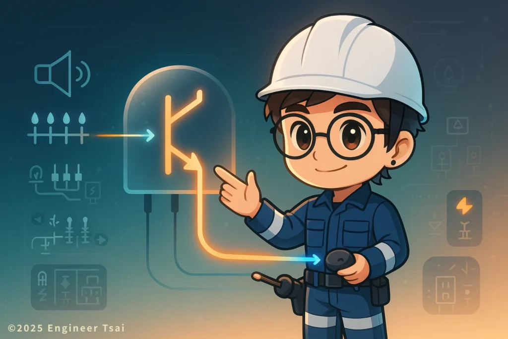
Watch first: what is a transistor and how can a small current control a big one?
This short video gives you a very down-to-earth introduction to what is a transistor and how it works.
You’ll see how it can use a tiny current to control a much larger current, and how the same device can act as both a signal amplifier and an electronic switch.
What is a transistor? A one-sentence answer first
If someone asks you, “What is a transistor?” you can start with this:
A transistor is a semiconductor device that uses a small current to control a larger current. It can work as a signal amplifier or an electronic switch, and it’s one of the basic building blocks of modern electronics.
In a typical home, office, or workshop, you’ll find transistors hiding inside:
- Headphones and small speakers
- Computer motherboards and graphics cards
- Phone and laptop chargers
- AC or HVAC control boards
- Industrial control boards and PLC I/O modules
They’re everywhere—you just don’t usually notice them.
In this article, we’ll walk through transistors in a “low-formula but solid-concept” way, so that the question “what is a transistor?” turns into a clear picture in your mind instead of a vague exam question:
- What the structure looks like, and what each of the three pins does
- How it actually amplifies current or acts like a switch
- A simple LED experiment that shows “small current controlling big current” right in front of you
In textbooks and datasheets, this kind of transistor is often called a
BJT (Bipolar Junction Transistor). Sometimes people just say “bipolar transistor” or simply “transistor”.
When you see those names, they’re talking about the same family of devices.
If you want a more formal, textbook-style explanation later, you can also check the
Transistor article on Wikipedia and similar semiconductor references.
Basic transistor structure: Base, Collector, Emitter
For now, when you’re trying to explain what is a transistor in simple words, think of it as a “super-powered electronic switch with gain”.
A BJT is made from three layers of semiconductor, which correspond to three terminals:
- Base (B) – where you “give the command”.
It only needs a small current to do that. - Collector (C) – where the main current comes in; you can imagine it as “collecting” current from the supply.
- Emitter (E) – where the main current leaves; it “emits” the current into the rest of the circuit.
Depending on how those three layers are arranged, BJTs come in two main types:
- NPN transistor (N–P–N)
Very common in small-signal amplifiers and digital control circuits. You’ll see it everywhere in hobby projects and low-side switching. - PNP transistor (P–N–P)
More common in certain power topologies or high-side switching. Often used together with NPN devices in complementary pairs.
A quick way to remember the behavior:
- NPN – “Add a little positive current into the base and current flows from C → E.”
- PNP – “Pull the base a bit lower and current flows from E → C.”
Once you memorize this, schematic symbols and example circuits will make a lot more sense.
How does a transistor amplify current? – The three operating regions
The core superpower of a transistor is this:
It uses a very small base current (IB) to control a much larger collector current (IC).
Depending on how you bias the device, it roughly works in three operating regions:
- Cutoff region
- The base current is essentially zero; the B–E junction is not forward-biased.
- The transistor is off. The path from C to E is basically open-circuit, like a switch that isn’t pressed.
- Saturation region
- The base current is large enough that the transistor is fully turned on.
- The C–E path looks like a low-resistance connection.
- In digital circuits, this is treated as a fully “on” electronic switch (for example, pulling an output node to ground).
- Active region
- The base current is set to a moderate value, so the transistor sits in a linear amplification region.
- In this region:
IC ≈ β × IB - Where:
- IC is the collector current
- IB is the base current
- β (also written hFE) is the current gain, often somewhere between 20 and a few hundred for typical small-signal BJTs.
In the active region, you use transistors for:
- Audio amplification
- Sensor signal amplification
- RF (radio-frequency) stages
When you switch the device back and forth between cutoff and saturation, you’re using it as a fast electronic switch.
Common everyday uses of transistors
Once you have a rough idea of what is a transistor, the next question is where you actually see it in everyday life. The examples below show how that tiny device quietly does a lot of heavy lifting in modern electronics.
1. Current / voltage amplification – make tiny signals audible and visible
In a lot of electronic products, the original signal is extremely weak. You need several stages of amplification before the signal can drive a speaker or a bigger circuit. For example:
- Headphone amplifiers
A low-level audio signal from a phone or laptop gets amplified so headphones or small speakers have enough current to move the drivers. - Sensor front-end stages
Signals from sensors like temperature probes, light sensors, or microphones are often much too small to use directly.
You first feed them into BJT or op-amp stages to boost the signal, and then send them into an ADC or microcontroller.
BJT stages are still a classic way to build simple preamps and front ends.
2. Electronic switches – using small currents to drive heavy loads
In digital and microcontroller applications, transistors are often used as driver devices. For example:
- Driving LED strips or small motors from a microcontroller
An Arduino or ESP32 pin can only supply a few tens of milliamps.
You pass that small current into a transistor, which then switches a much larger current to drive a relay coil, fan, or LED strip. - Relay driver circuits
A low-voltage control signal turns on a transistor.
The transistor energizes the relay coil, and the relay contacts then switch 120 V / 240 V AC loads on or off.
(The transistor never directly touches the mains voltage; it just controls the relay.)
3. Oscillators and signal processing
With the right combination of resistors, capacitors, and sometimes transformers, a transistor can also generate and process various waveforms:
- Clock oscillator circuits
Multi-vibrator circuits built from a few transistors can generate square waves for timing. - Modulation and demodulation
In radio and communication circuits, BJTs help with tasks like amplification, modulation, mixing, and detection.
If you’re already comfortable with the basics and want to dive deeper into formulas and real-world circuits, you can explore longer BJT tutorials on sites like All About Circuits – Bipolar Junction Transistors or the Transistor article on Wikipedia.
Simple experiment: using an NPN transistor to “control a big current with a small one”
Here’s a hands-on experiment that makes the idea of what is a transistor very concrete:
When the base gets a small current, the LED turns on. When the base gets no current, the LED turns off.
⚠️ Safety note:
Do this experiment with battery power only.
Do not connect this simple circuit directly to 120 V / 240 V AC mains.
Parts you’ll need
- One NPN transistor (for example, 2N3904)
- One LED
- A 3 V battery pack (two AA cells in series, or a 3 V coin-cell module)
- One 1 kΩ resistor (for the base)
- One 330 Ω resistor (in series with the LED)
- A few jumper wires and a breadboard (optional, but makes life easier)
Wiring steps (common emitter configuration)
- Set up the main current path
- Connect the emitter (E) of the NPN transistor to the negative terminal of the battery.
- Put the LED and 330 Ω resistor in series between the collector (C) and the positive terminal of the battery:
Battery + → 330 Ω → LED → Collector (C)
- Set up the base control path
- Connect one end of the 1 kΩ resistor to the positive terminal of the battery.
- Connect the other end of that resistor to the base (B) of the transistor.
- Turn it on and off
- When the 1 kΩ resistor is connected to the battery positive, a small base current flows into the transistor → the LED turns on.
- When you disconnect the base lead, the transistor turns off → the LED goes dark.
What to observe and how to think about it
- Base has current:
The transistor moves into the active / saturation region.
A small base current lets a larger collector current flow through the LED, so you see it light up. - Base has no current:
The transistor goes back to cutoff.
The C–E path is practically open-circuit, and the LED turns off.
That’s the classic one-line summary of a BJT:
“Use a small current to control a larger current.”
Whenever you see a transistor symbol on a schematic in the future, picture this simple LED circuit in your head. It’ll make the bigger diagrams feel much less intimidating.
Common questions about transistors (FAQ)
Q: Can you explain what is a transistor in one sentence?
A:
Think of it as a semiconductor device that uses a small current to control a larger current, acting as an electronic switch or amplifier.
In the active region, it amplifies weak signals.
When it’s switched between cutoff and saturation, it behaves like a very fast electronic switch.
Q: What’s the difference between NPN and PNP? How do I choose in practice?
A:
Here’s the short version:
NPN
The most common setup is a common-emitter NPN.
You feed a small positive current into the base, and current flows from C → E.
NPN devices are especially popular for low-side switching, where the transistor connects the load to ground.
PNP
Often used in high-side switching.
When you pull the base lower, current flows from E → C toward the load.
If you’re building typical low-voltage projects—like a microcontroller driving LEDs, relays, or small motors—NPN transistors are usually the first, simplest choice.
They’re easier to reason about, and most beginner tutorials use NPN examples.
Q: How can I tell which pin is Base, Collector, and Emitter?
A:
Different transistor part numbers can have different pinouts, even if the package looks the same. So the first step is always to check the datasheet.
If you don’t have the datasheet in front of you:
Take a clear photo of the part number with your phone and look it up later for the pinout diagram.
Use a multimeter in diode test mode to find which two pins behave like the B–E and B–C junctions, then infer which pin is Base, which is Collector, and which is E.
But if you’re not sure, don’t plug a mystery transistor into a high-voltage or mission-critical circuit right away.
Test it in a small, low-voltage experiment first—that’s much safer.
Q: When a transistor fails, what symptoms do I see in the circuit?
A:
There are two very common failure modes:
Short-circuit failure
The transistor’s internal junctions break down so that C–E is essentially shorted.
This can blow fuses, overheat power supplies, or make a device trip protection as soon as it’s turned on.
Open-circuit failure
The transistor no longer conducts when it should.
In an amplifier, the gain collapses or you lose the output signal.
In a driver stage, relays won’t pull in, LEDs won’t light, motors don’t spin, even though the control signal is present.
During troubleshooting, you can use a multimeter’s diode mode to check whether the B–E and B–C junctions still show a normal forward voltage drop.
That gives you a rough idea of whether the transistor is still alive.
Summary and next steps
By now, you’ve seen the key ideas behind BJTs, so the question “what is a transistor” should be much easier to answer in your own words:
- What a transistor is:
A semiconductor device that uses a small current to control a larger current, working as either an amplifier or an electronic switch. - How it does it:
Through its Base, Collector, and Emitter terminals, biased into cutoff, saturation, or the active region. - Where it shows up:
From headphone amps and power supply boards to AC control boards, industrial control boxes, and microcontroller driver circuits—you’re surrounded by transistors all the time. - How you can prove it to yourself:
With one NPN transistor, a couple of resistors, and an LED, you can build a tiny circuit where a small base current clearly controls a larger LED current.
If you’re just getting started with electronics, or you’re thinking about moving toward electronics repair, circuit design, electrical work, or automation, understanding transistors will make a lot of schematics suddenly click into place.
Recommended next reads:
- “DIY Voltage and Current Basics: Understanding the Relationship”
Build a clear mental picture of “voltage pushes current”, and it becomes much easier to understand what a transistor is actually doing inside your circuit. - “What Is a Diode? How It Controls Current and Shapes Electronic Circuits”
First understand a simple “one-way valve for current”, then move on to the transistor as a device that can control how much current flows. - “MOSFET vs BJT: Which Switch Is Better for Your Project?” (coming soon)
Once you get into power supplies and motor control, you’ll constantly be choosing between MOSFETs and BJTs. - “How to Choose the Right Transistor for Your Circuit” (coming soon)
A practical guide to reading transistor datasheets—voltage ratings, current, power dissipation, gain, and package types.
💡 If you still have questions about how transistors are used in real-world circuits, feel free to drop them in the comments.
You can also subscribe to the newsletter or blog updates if you want to slowly turn these components into tools you’re comfortable using. 🚀
Read next in this topic
- What Is Electricity ? Everything You Need to Know
- Current & Voltage for DIY Enthusiasts : Unlock the Basics
- AC vs DC: What’s the Difference and Why It Matters (From Phone Charging to 120 V Home Power)
- Basic Parts of an Electric Circuit (Power Source, Wires, Loads)
- Conductor vs Insulator: How Your Home’s Wiring Keeps You from Getting Shocked
- Ohm’s Law Explained: V = IR for 120V Home Circuits
- What Is a Resistor? How It Works, Types, and How to Choose the Right One
- Series vs Parallel Circuits: Simple Guide for Home Wiring (With Formulas & Examples)
- How Electromagnetic Wave and Electricity Shape Modern Technology
- What Is Voltage? Simple Definition, Everyday Examples, and Safety Tips
- What Is a Battery? How It Works, Types, and Everyday Uses Explained
- What Is Ampere’s Law? A Visual Guide to How Current Creates Magnetic Fields
- What Does a Capacitor Do? Uses, Energy Storage, and Everyday Examples
- Types of Electrical Wire: How to Choose the Right One for Your Home
- How AC Power Is Converted to DC: What’s Really Inside Your Phone Charger?
- Electrical Energy Conversion: How Energy Transforms for Everyday Use
- Magnetic Field and Current: The Core Relationship Behind Motors, Generators, and Wireless Charging
- How Do Magnets Work? From Fridge Magnets to Maglev Trains
- What Is Inductance? Inductor Basics for Real-World Circuits
- What Is Impedance? A Plain-Language Guide to Resistance, Inductive Reactance, and Capacitive Reactance